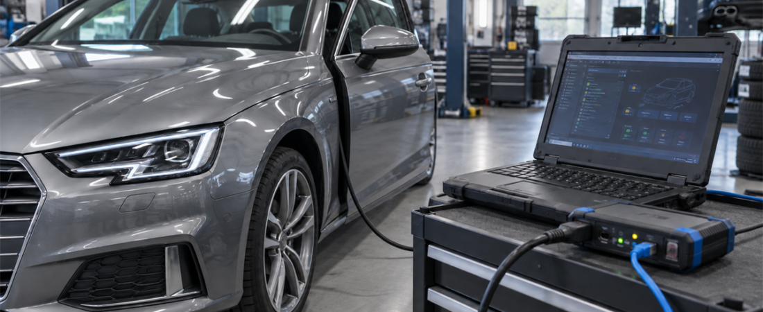
Modern diagnostic software may connect to one vehicle over CAN and to another over Ethernet, even when both sessions begin at a familiar diagnostic connector. That difference matters when a workshop buys an interface, troubleshoots a connection, or prepares for a large software update.
The useful way to understand DoIP vs CAN bus diagnostics is not to treat them as competing scan-tool brands. CAN is a vehicle network technology. DoIP is a standardized method for carrying diagnostic communication over Internet Protocol, commonly using automotive Ethernet. A newer vehicle can use both at the same time, with a gateway routing messages between Ethernet and CAN-based subnetworks.
CAN and DoIP Operate at Different Layers
Controller Area Network, or CAN, is a serial communication system designed for reliable, real-time control between electronic modules. It is standardized in the ISO 11898 family. The current ISO 11898-1:2024 edition covers the CAN data-link layer and physical coding sublayer, including newer frame formats alongside Classical CAN.
Diagnostic services can run over CAN using transport rules such as ISO 15765-2. This is often called DoCAN. The diagnostic application may use Unified Diagnostic Services, or UDS, while CAN carries the messages between the tester, gateway, and control module.
Diagnostics over Internet Protocol, or DoIP, takes a different transport path. ISO 13400-2:2025 defines vehicle discovery, connection establishment, routing, status information, and diagnostic data exchange using IP with TCP and UDP. ISO 14229-5:2022 defines how UDS is implemented on IP networks. In other words, many familiar diagnostic functions remain recognizable; the network carrying them changes.
How a CAN Diagnostic Session Works
In a typical CAN-based session, the laptop talks to a vehicle communication interface, or VCI. The VCI converts the software’s requests into messages suitable for the vehicle bus. A gateway may then forward each request to the correct module.
CAN remains practical because it is mature, robust, and present across a huge vehicle population. It handles short control and diagnostic messages efficiently. However, Classical CAN frames carry small payloads, so transferring a large calibration or software package requires many frames plus transport-layer segmentation. CAN FD improves payload size and data-phase speed where the complete path supports it, but a legacy interface cannot gain CAN FD capability through a software setting alone.
How a DoIP Diagnostic Session Works
A DoIP-capable tester first joins the vehicle’s IP network. It can discover the vehicle or DoIP gateway, establish a connection, activate a diagnostic route, and address the required control unit. The gateway may deliver the request to an Ethernet ECU or translate and route it to a module on CAN or another internal network.
The wired DoIP interface defined by ISO 13400-3 is based on 100BASE-TX Ethernet. That higher-capacity path is especially useful for large data transfers, rapid full-vehicle scans, and software-intensive vehicles. It does not guarantee that every job will finish a fixed number of times faster: ECU processing, gateway routing, security access, storage write speed, server availability, and the OEM application can all become the limiting factor.
DoIP vs CAN Bus Diagnostics at a Glance
| Workshop question | CAN-based diagnostics | DoIP diagnostics |
|---|---|---|
| Underlying connection | CAN physical and data-link layers through a compatible VCI | IP networking, commonly over diagnostic Ethernet |
| Typical strength | Reliable access to established vehicle platforms and CAN subnetworks | Higher bandwidth for large scans, data sets, and software transfer |
| Required hardware | VCI with the correct CAN and, where needed, CAN FD support | DoIP-capable VCI or an OEM-approved direct Ethernet connection |
| Common failure area | DLC power, VCI driver, bus wiring, gateway, or protocol selection | Ethernet link, IP addressing, discovery, routing activation, firewall, or gateway |
| Security | OEM access rules still apply | OEM access rules still apply; DoIP is not a security bypass |
What Workshops Should Buy in 2026
Match the interface to the jobs you perform
A workshop serving mixed model years usually needs both capabilities. Do not replace a working CAN interface merely because a product page advertises Ethernet, and do not assume an older VCI supports DoIP because it has a network socket. Confirm the exact hardware revision, firmware, OEM software version, vehicle platform, and intended function.
Verify support before purchasing
Use this purchasing checklist:
- Vehicle coverage: verify by make, model, model year, and platform, not only by brand.
- Transport support: look for explicit Classical CAN, CAN FD, and DoIP support where those are required.
- OEM approval: programming may require a validated VCI, current software, subscription, and authorized security access.
- Connection method: determine whether the application expects a direct Ethernet cable, a DoIP VCI, or another OEM interface.
- Update path: confirm that interface firmware and drivers remain supported on the workshop laptop.
Our J2534-, OEM VCI- ja ELM327-protokollien vertailu explains why interface class matters just as much as the software name.
A Safe Connection Workflow
- Identify the required path. Check current OEM service information for the VIN and task. Reading codes may use one path while programming requires another.
- Stabilize power. Use an appropriate battery support unit for programming and follow the OEM voltage and current requirements. Keep the laptop powered and disable sleep.
- Connect approved hardware. Inspect the diagnostic connector, Ethernet lead, VCI cable, and USB or network connection before starting.
- Control the network. For DoIP, use the OEM-recommended adapter settings. Disconnect unnecessary VPNs and network bridges. Add only the required trusted firewall exception instead of disabling security globally.
- Confirm discovery and identification. Verify that the application finds the correct VIN, gateway, and interface before opening a programming session.
- Scan and save evidence. Record a complete pre-scan and voltage status. If a module is missing, investigate before writing software.
- Keep the path stable. Do not unplug cables, switch adapters, close the laptop, or allow an update to restart the computer during coding or flashing.
For higher-risk work, review our ECU coding and programming safety checklist before the session.
Troubleshooting the Right Layer
When CAN communication fails, start with vehicle voltage, diagnostic-connector power and grounds, cable condition, VCI detection, driver status, and the selected protocol. Follow the OEM test plan before measuring network resistance or waveform quality, because connected modules and network topology affect the result.
For DoIP, first confirm an Ethernet link, then IP address assignment, vehicle discovery, routing activation, and the selected VIN. A corporate firewall, active VPN, incorrect network metric, outdated VCI firmware, or sleeping gateway can stop a session even when the cable is good. If the vehicle is discovered but one ECU remains unavailable, the problem may be behind the gateway rather than on the Ethernet link.
Our step-by-step guide to fixing a no-communication error helps separate vehicle power, interface, driver, protocol, and gateway faults.
The 2026 Takeaway
DoIP is becoming essential for high-bandwidth diagnostics and software-heavy platforms, while CAN remains deeply embedded in vehicles and workshop workflows. The practical choice is therefore not DoIP or CAN. It is a diagnostic stack that supports the transport required by each vehicle, uses current OEM information, and keeps power, hardware, networking, and security access under control. Buy for verified coverage, test the complete connection path, and never begin a programming job until the vehicle and software agree on how they will communicate.
 English
  German
  Spanish
  Italian
  French
  Hebrew
  Dutch
Dutch  Finnish
  Norwegian
  Swedish
  Polish