
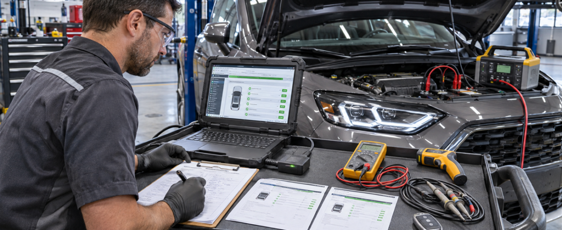
Automotive Diagnostic Workflow Template: From Customer Complaint to Verified Repair
An automotive diagnostic workflow template turns a customer complaint into a repeatable evidence trail. It helps the technician define the symptom, preserve baseline data, develop a test plan, isolate the root cause, document the repair, and prove that the original concern is corrected.
The template below can be added to a repair order, digital inspection, or workshop standard operating procedure. Adapt individual tests to the vehicle and always follow current OEM service information, safety instructions, and authorization requirements.
1. Capture the Customer Complaint Precisely
Record the customer’s words before translating them into technical language. “Car runs bad” is not a testable complaint. Ask what the driver feels, hears, sees, or smells; when it occurs; how often; how long it lasts; and what changed before it began.
- Vehicle: VIN, mileage, model, engine, transmission, and relevant equipment
- Symptom: Exact description and affected system
- Conditions: Speed, temperature, load, weather, road, fuel level, and key cycle
- Frequency: Constant, intermittent, first start, hot restart, or after a specific event
- History: Recent repairs, battery events, accessories, collision, software updates, and previous attempts
- Authorization: Approved diagnostic time, road test, data access, and sublet work
Identify any immediate safety concern before operating the vehicle. Do not road-test a vehicle with unsafe brakes, steering, tires, high-voltage damage, fuel leakage, or another condition that makes testing hazardous.
2. Verify the Concern
Reproduce the complaint under the customer’s conditions when safe. Record what happens rather than writing “verified.” Note warning lamps, messages, sounds, vibration, performance, gauge readings, environmental conditions, and the exact point where the symptom begins.
If the vehicle appears to operate normally, review the owner’s manual and system description. Compare with a known-good vehicle where practical. A normal operating characteristic should be explained and documented, not repaired by replacing parts.
For an intermittent condition, create a safe reproduction plan using the freeze-frame and live-data workflow. Do not clear evidence merely to see whether the fault returns.
3. Establish and Save the Baseline
Perform preliminary checks before focused diagnosis. Confirm battery state, system voltage, fluid levels, fuses, visible damage, connectors, grounds, aftermarket equipment, and obvious signs of previous work. Review service history, campaigns, recalls, and repeat visits.
Run a full-vehicle scan with appropriate equipment and save the original report. Record all communicating and missing modules, current and history DTCs, freeze-frame data, code status, module identification, and relevant software levels. The guide to DTC status explains why current, pending, history, confirmed, and permanent codes require different conclusions.
Baseline fields:
- Date, time, mileage, and technician: ____________________
- Battery voltage and test condition: ____________________
- Scan tool, interface, and software version: ____________________
- Warning lamps and messages: ____________________
- DTCs and missing modules: ____________________
- Attachments saved: Pre-scan, freeze-frame, photos, video, and graphs
4. Research Before Building the Test Plan
Use the VIN and exact configuration to access current OEM service information. Read system description and operation, wiring diagrams, connector views, DTC charts, specifications, test conditions, technical bulletins, and programming or calibration requirements.
Separate symptoms from causes. A communication code may result from low voltage, missing power, damaged wiring, or another module pulling down the network. A sensor code does not automatically condemn the sensor.
Write a short hypothesis and the next discriminating test:
- Suspected system or circuit: ____________________
- Reason for suspicion: ____________________
- Test and connection points: ____________________
- Expected result and specification: ____________________
- Next step if pass / next step if fail: ____________________
5. Test the System and Record Real Values
Start with tests that divide the problem efficiently and minimize disturbance. Depending on the system, check loaded power and ground, voltage drop, reference voltage, signal integrity, current, resistance under correct power-off conditions, live-data relationships, actuator response, network waveforms, fuel pressure, compression, vacuum, or mechanical timing.
Record the measured value, unit, specification, operating condition, test point, and tool. “Power good” is weak documentation; “12.42 V at B+ and 42 mV ground-side drop under commanded load” is reproducible evidence. GM service guidance similarly calls for actual DTCs, readings, specifications, circuit numbers, and descriptive locations rather than vague comments.
Do not replace a component until the test result supports a root cause or the published procedure directs replacement. If results conflict, recheck tool setup, test conditions, connector contact, and the original complaint.
6. Isolate the Root Cause and Obtain Authorization
State the failed component, circuit, software condition, mechanical fault, or external influence and explain how the evidence proves causation. List any separate pre-existing concerns discovered during diagnosis. Provide an estimate covering the repair, required one-time-use parts, programming, calibrations, fluids, alignment, and verification.
Grundursache: ____________________
Evidence: ____________________
Recommended correction: ____________________
Customer authorization and time: ____________________
7. Perform and Document the Repair
Follow the OEM procedure, including torque specifications, replacement fasteners, connector locks, cleanliness requirements, coding, programming, initialization, relearns, and calibrations. Record part numbers, software or calibration identifiers, measurements, and deviations from the original plan.
If the repair changes, stop and obtain additional authorization. Preserve replaced parts and supporting evidence according to shop policy, warranty rules, and customer instructions.
8. Verify the Repair Under the Same Conditions
Repeat the test that originally failed and reproduce the customer’s operating conditions. Complete required drive cycles, active tests, calibrations, readiness checks, road tests, or warm-up and cool-down cycles. A cleared code is not proof of repair.
Perform a final full scan and compare it with the baseline. Confirm that expected modules communicate, related DTCs do not return, no new faults were introduced, and unrelated items are documented. Use the pre-repair and post-repair report comparison to create a defensible record.
9. Close the Repair Order Clearly
Summarize the complaint, cause, correction, and verification in plain language. Attach pre-scan and post-scan reports, test readings, graphs, photos, programming or calibration results, alignment data, and road-test details. Identify declined, pre-existing, or unresolved conditions and record how the customer was notified.
Final release fields:
- Original complaint reproduced: Yes / No / Intermittent
- Root cause confirmed by: ____________________
- Repair performed: ____________________
- Verification conditions and result: ____________________
- Final scan and calibrations attached: Yes / No / Not required
- Remaining recommendations explained: ____________________
A disciplined workflow does not make every diagnosis simple. It makes each decision visible, reduces repeated testing and unnecessary parts, and gives the next technician a reliable starting point if the vehicle returns.
 English
 German
 Spanish
 Italian
 French
 Hebrew
 Dutch
 Finnish
 Norwegian
 Swedish
 Polish