
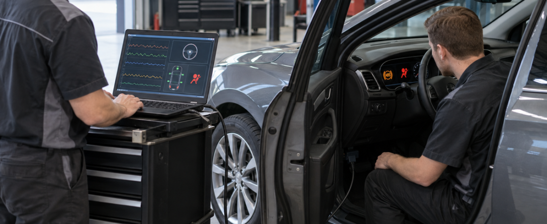
ABS and airbag warning lights are easy to misunderstand because the vehicle may still drive and appear normal. An illuminated ABS lamp can mean basic braking remains available while anti-lock braking is disabled. An airbag lamp can mean part of the supplemental restraint system may not protect occupants as designed. Neither warning should be erased without diagnosing the cause.
Professional diagnostic software finds faults that a generic engine-code reader cannot see. It communicates directly with the anti-lock brake system (ABS), electronic stability control, airbag or supplemental restraint system (SRS), occupant classification, and related body modules. The goal is not merely to turn off a lamp, but to prove that the safety system is operational.
What the Warning Lights Mean
Warning lamps normally illuminate briefly during the ignition self-check. If the ABS lamp stays on or appears while driving, the system has detected a malfunction. Honda’s current owner guidance states that normal braking may remain, but without the anti-lock function. Traction control and stability control may also be limited because they share wheel-speed and hydraulic components.
If the red brake warning appears with the ABS lamp, treat the condition more urgently. It may indicate a base-brake, hydraulic, fluid-level, or electronic brake-distribution problem. Follow the owner’s manual and stop safely when instructed rather than assuming the vehicle simply lost ABS.
An airbag or SRS lamp that does not complete its normal self-check, remains illuminated, or begins flashing indicates a restraint-system fault. Depending on the design, affected components can include airbags, seat-belt pretensioners, crash sensors, occupant detection, seat-position inputs, or the control module. Airbags supplement seat belts; they do not replace them.
Why a Basic OBD2 Reader Is Not Enough
Generic OBD2 emissions functions focus on powertrain faults. ABS and SRS diagnosis requires manufacturer-level access to chassis and body modules. A suitable scan platform can read system-specific DTCs, code status, event details, live data, module identification, test plans, and calibration functions.
The first letter of a code also matters. ABS faults are often chassis codes, while restraints may use body or network codes. Our guide to P, B, C, and U diagnostic trouble codes explains how code families and status help define the next test.
Common ABS Warning-Light Causes
- Wheel-speed sensor or wiring fault: an open circuit, short, damaged connector, or debris can remove one wheel signal.
- Encoder or tone-ring damage: rust, cracks, contamination, incorrect air gap, or a damaged magnetic wheel-bearing encoder can create dropouts.
- Wheel bearing or tire problem: excessive play, mismatched tire sizes, or a large circumference difference can make speeds disagree.
- Low system voltage: a weak battery, charging fault, or poor ground can create multiple module and communication codes.
- Calibration issue: steering-angle, yaw-rate, or brake-pressure sensors may need calibration after alignment, suspension, or module work.
- Hydraulic or module fault: pump motor, valve, pressure sensor, power supply, or internal control-unit problems require guided testing.
Common Airbag Warning-Light Causes
- Loose, damaged, or disturbed wiring beneath a seat
- Seat-belt buckle or pretensioner circuit faults
- Steering-wheel clockspring or driver-airbag circuit problems
- Occupant classification or seat-position sensor faults
- Impact-sensor wiring, water intrusion, or corrosion
- Low-voltage history after a weak battery or jump start
- Previous collision damage, deployed components, or stored crash information
Do not replace a seat mat or airbag based on a description alone. BMW service guidance for certain occupant-detection faults, for example, directs technicians to run the linked test plan, inspect for moisture, and watch the occupancy status change before replacing parts. The DTC identifies a circuit or condition; testing identifies the cause.
Step-by-Step Diagnostic Workflow
- Confirm every warning. Record which lamps appear during self-check, which remain on, whether a message is displayed, and what happened before the fault began.
- Check recalls and repair history. Verify the VIN for open safety recalls and ask about collisions, seat removal, wheel-bearing work, alignment, battery replacement, water leaks, and accessory installation.
- Stabilize electrical voltage. Test the 12-volt battery and charging system. Connect approved support equipment if the OEM procedure or extended diagnostic session requires it.
- Run a complete pre-scan. Save DTCs from all modules with status and available freeze-frame or event data. Network and low-voltage codes can connect symptoms across systems.
- Follow the OEM test plan. Use wiring diagrams, connector views, pin data, specified tools, and current service precautions for the exact VIN.
- Review live data. Compare all four wheel speeds, brake-switch state, steering angle, yaw data, system voltage, buckle switches, seat occupancy, and other relevant inputs.
- Inspect the suspected area. Check wiring routing, connectors, grounds, water damage, wheel bearings, sensor mounting, tone rings, tires, and evidence of earlier repairs.
- Repair and calibrate. Correct the root cause, replace only confirmed failed parts, and perform required coding, initialization, steering-angle calibration, or occupant-system calibration.
- Clear and verify. Clear faults only after repair, complete the specified ignition cycle or road test, and run a final full-vehicle scan.
How Live Data Finds ABS Faults
Graph all wheel speeds together during a controlled low-speed road test. One signal that drops to zero, spikes, or differs at the same vehicle speed points toward that wheel’s sensor, encoder, wiring, bearing, or tire. A fault that appears only while turning or over bumps may indicate harness movement or changing sensor clearance.
Do not condemn the sensor immediately. Compare the scan data with circuit tests specified by the manufacturer and inspect the encoder carefully. Intermittent faults benefit from the recording methods in our freeze-frame and live-data diagnostic guide.
How Scan Data Finds Airbag Faults
SRS data can reveal whether the module sees a seat occupied, a buckle latched, a component circuit outside its expected range, or a control unit with crash-related status. It can also show whether a fault is current or stored from a temporary low-voltage or connector event.
Restraint circuits require special precautions. Disconnect and de-energize the system exactly as the OEM procedure states before component work. Do not probe inflator or pretensioner circuits with a test light, jumper wire, or ordinary meter unless the repair information specifically authorizes the method and tool. Accidental deployment can cause serious injury.
Clearing Codes Is Not a Repair
If the warning returns, the monitored fault remains or the required initialization is incomplete. Never install resistors, bypass devices, or software changes to hide a restraint fault. Deployed airbags cannot be reused, and NHTSA recommends proper replacement by qualified technicians.
Attach the initial and final reports to the repair order. The documentation process in our pre-scan versus post-scan guide helps prove that modules communicate, safety faults are resolved, and no new codes were introduced.
Conclusión final
ABS and airbag warning lamps identify systems that may no longer provide their intended protection. The right diagnostic software reaches the correct modules, preserves fault context, graphs sensor data, and guides required calibrations. Pair those capabilities with physical inspection, current OEM procedures, and a verified post-scan. That is how a workshop finds the real cause instead of merely hiding the warning.
 English
  German
  Spanish
  Italian
  French
  Hebrew
  Dutch
Dutch  Finnish
  Norwegian
  Swedish
  Polish